louvered contact band for every fprm of connector design


Louvered Contact Band
- Technology

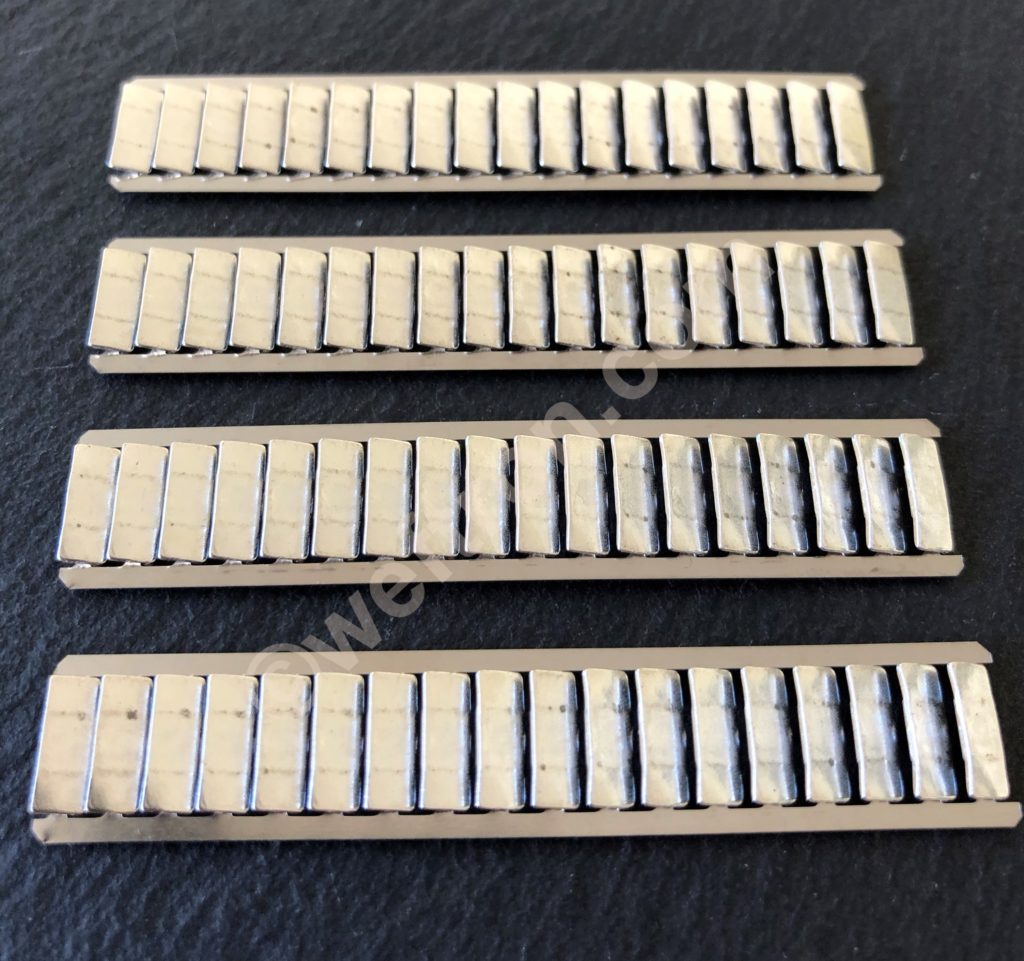
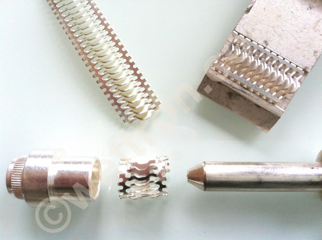
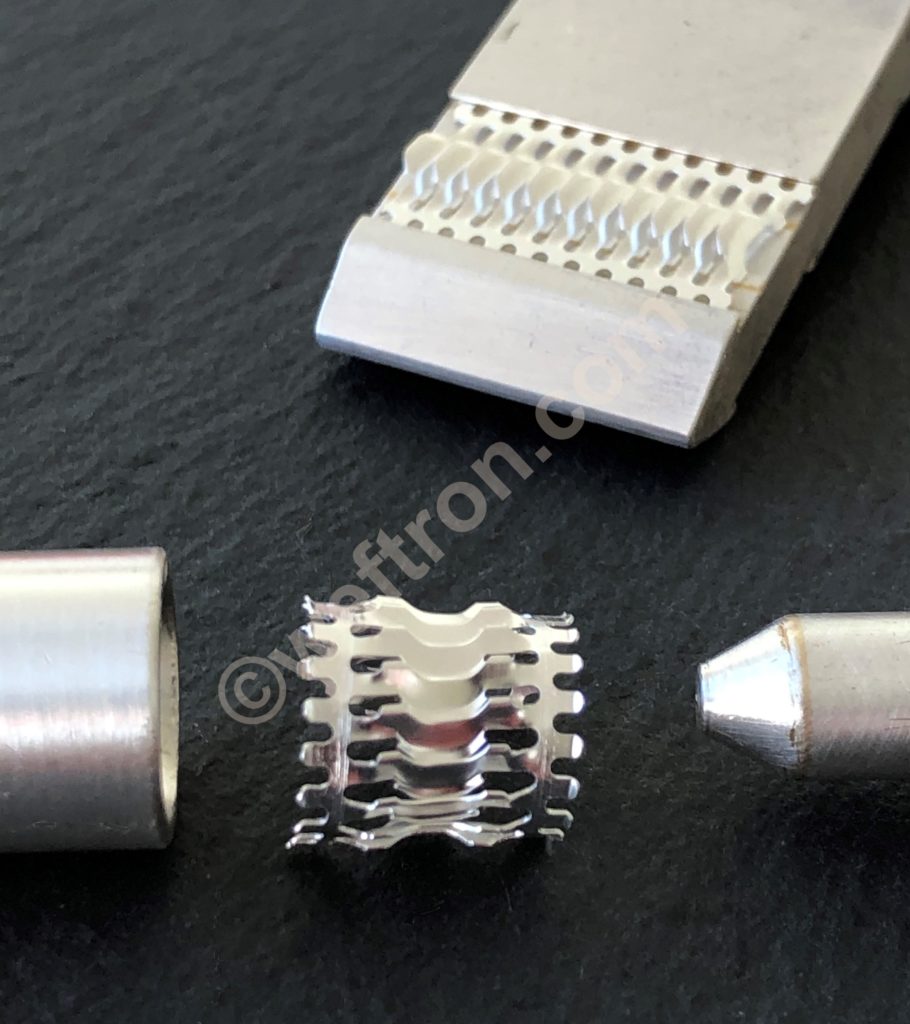
louvered contact bands are precision stamped metal strips. Specifically used for electrical power and signal transmission between metal components of an electrical connection. Markedly louver shaped contact bridges are arranged in parallel along the length of the stamped metal band. Similarly to ladder rungs they are attached to the side rims of the metal strip.  So these louvers perform as individual mechanical torsion springs when in use between two mating metal surfaces as well as electrically conduction elements.

Mating metal components

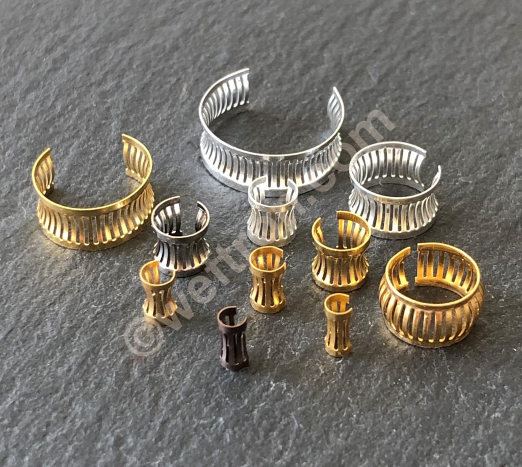
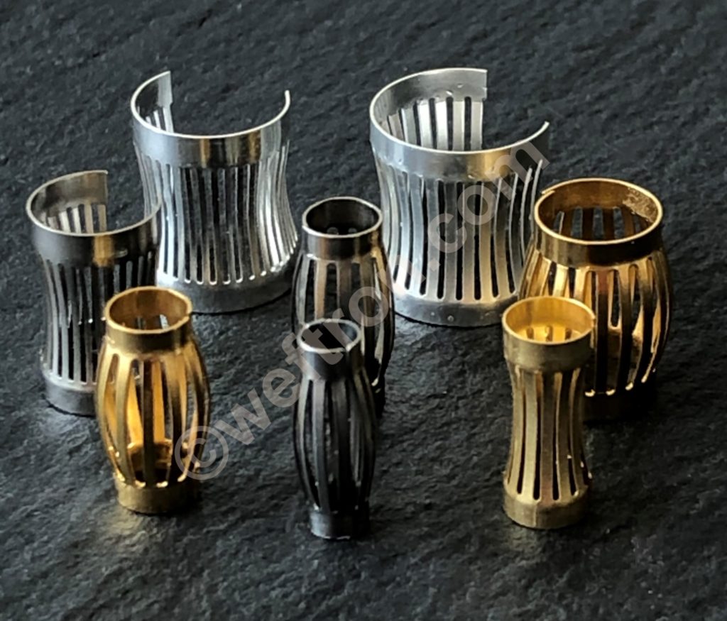
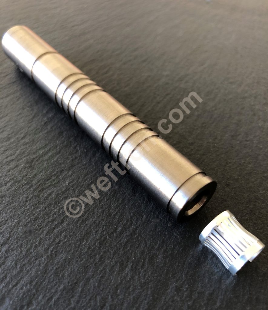
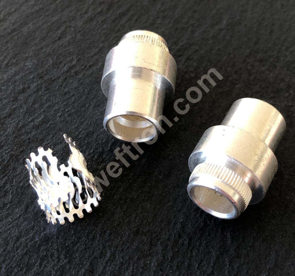
The mating metal connector components may be round in shape as for example in pin and socket connectors. Furthermore they may be flat as for example with fork and knife type contacts such as busbar connectors. Or they may also be used in between two flat mating surfaces such as pressure plate connections. So the louvered contact band will be fixed to either of the mating components. Hence it will be compressed to working height when both components are mated. In this mated condition the individual contact bridges will exert even and precisely defined mechanical spring force between the two components and will perform as the functioning conducting elements for passing electrical current.

Each of the contact bridges act as precisely defined contact points that represent low resistance connections arranged in a parallel circuit. In reference to Ohm's law the more contact points per foot print the lower will be the total contact resistance of the connector.

Electrical connectors are often used under extreme mechanical and environmental conditions. With high current loads on small footprint. Subjected to heavy vibrations as well as continuous micromotion. Extreme temperatures and aggressive environments.

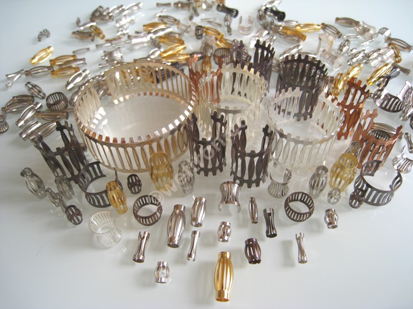
Such conditions require high quality electrical connections. Connectors with Louver_tron contact band by weftron.com are the best choice to provide High Performance Contacts for those special requirements. Louvered contact bands may be classified in two categories. - Single component contact bands - which are stamped from one material and - Multi Component contact bands - which are composed of a carrier strip of one material with attached individual contact plates of another material.
Continue reading about the materials used in louvered contacts.....


louvered contact band for high power connectors

Louvered Contact Band
- Materials

The predominantly used material for louvered contact band is a special Beryllium Copper Alloy. Especially when speaking about  - Single Component Contact Bands -.  Although pure grade copper would offer much better electrical conduction the mechanical spring properties of hardened CuBe alloy are required for the functionality of a pluggable electrical connection. Albeit the lesser electrical conductivity CuBe is a very good thermal conductor. Beneficial for heat soaking the temperature away to the metal components of the connector that will develop by material inherent electrical resistance at each contact point .

Contact resistance

Further improvement to lower contact resistance may be achieved in selecting suitable surface treatments for the louvered contact band. Any oxide layer on metal surfaces will act as an electrical insulator. Although Louver_tron louvered contact band is designed to break this oxide layer and wipe it away from the contact points during the mating of the connecting parts the oxide layer of bare copper is a quite hard. Increasing the spring force will help in wiping such hard insulating layers. This however comes at the cost of damaging the surface of the mating component after a relatively low number of mating cycles.

For this reason it is recommended to use surface platings on the metal components and on the contact band. For high power low resistance electrical connection silver is the preferred choice. The conductivity of silver is ranking among the highest and the oxide layer of silver is quite soft. Allowing an optimum setting of spring force for high performance and long contact life.

Conductivity

Using pure grade copper for the conducting element between the connector components increases conductivity as compared to beryllium copper. However copper does not provide the necessary spring force that is functionally necessary. The way to solve this is by creating - Multi Component Contact Bands. Such such as weftron.com Louver_tron 112 or Louver_tron 108.
The spring feature in these Multi Component louvered contacts is provided by a separate carrier tape. Either made of stainless steel or of CuBe on which individual copper contact plates are mounted. Here again the surface treatment of choice for the contact plates is silver. The carrier tape does not necessarily require surface treatment. Unless when used in chemically hostile environments and gold will have to be used to protect all surfaces.

From an aspect of production effort and cost - Multi Component Contact Bands - are  much more complicated to produce than contact bands made from a single metal strip. Nevertheless there are applications when such - Multi Component Contact Bands - have no matching alternative. Due to their individual contact plates higher electrical and thermal conductivity and their larger mass they fulfill specifications with high short circuit currents when single component contact bands would fail.

Continue reading about the function of louvered contacts ....

contact band for busbar and for circular connectors

high current contact for for switchgear applications

Louvered Contact Band
- Function

Certain technical design provisions will need to be observed when using louvered contacts.  Similarly as it is the case for any mechanical spring application. So for a spring to function properly it will require a certain deflection. With no deflection there will be no spring force and no defined conduction between the two metal connector components. Over-deflection (over-compression) of the contact band elements however will damage them. Since they will be compressed into a mode of plasticity preventing the spring elements to return to their original uncompressed state.

Grooves for performance tuning

The best suited compression state of the contact elements is achieved by inserting them inside grooves. Such grooves will be machined into one of the mating metal components. The depth of this groove will limit the maximum compression of the contact spring elements. Therfore it will need to be machined with very tight tolerances. Thus achieving dependable repeatability of connector performance. In addition to spring tuning this groove will also hold the contact band in place. Different groove geometries may be chosen for certain applications.

For large socket diameters, for installations on a pin or for installation on a flat connector pair such a geometry may have the form of a dove-tail groove. For other applications it may be sufficient to use rectangular cut grooves. Although it is possible to use contact band without these grooves when taking great care to prevent uneven spring loading and over-compression during mating of the connector components this is not a recommended method for multiple mating cycles or for series applications.

With a contact band inserted and compressed between two electrically conducting components certain power transmission will be achieved.  It is safe to say that this power transmission will always be higher as compared to having a separable pin and socket connector of same size and material without using a spring element between the two. It is also safe to say that when observing best practice this level of power transmission and connector performance will be better than with most other available connector technologies.

Continue reading about the features of louvered contacts ....

louvered contact band for high power contacts

crown spring contact band for high power connectors

Louvered Contact Band
- Features

The final level of achievable power transmission when using crown spring contact band is dependent upon several parameters. Some of which are dependent upon best practice, the choice of material and quality of workmanship. Whereas others are variable by design and adoptable to application requirements.

The most common metals used are copper(1), aluminum(0.75) or brass(0.6). The numbers in brackets indicate a ball park figure for determining conductivity factors. Based on copper having a factor 1. Nevertheless it is possible to use any conductive material for the connector components.  Silver is the most common surface plating for high current applications. Whereas Gold will mainly be used for applications in aggressive environment. Although there are further reasons for gold platings. Such as in applications underlying micromotion between the connector components.

The current loading capability of the crown spring bands themselves is mainly influenced by their physical design. Also by the base material, the material thickness, surface plating and by the number of contact points per defined footprint. For two contact bands with all parameters being the same but with different number of contact points the one with more contact bridges will allow a higher load of power transmission.

This is one reason for Louver_tron 313 crown spring with a contact bridge spacing of 2mm being superior to other known crown spring contacts with a contact bridge spacing of 2.5mm or higher.

Heat dissipation

Contact Bands themselves are much lower in mass than the metal components in a connector. Therfore their thermal capacity is much lower. They depend upon the heat sinking capability of the metal connector components to quickly dissipate heat which will generate under load. This pertains to the choice of the material for the metal connector components as well as the minimum cross section of these components required to handle the load.
Nominal current rating for electrical contacts are usually quoted in conjunction with allowable temperature rise. A connector made of steel components for example and a max. permissible temperature rise of max. 40°C will reach this temperature limit at a lot lower current load than a connector made of copper components.

Continue reading about tuning performance parmeters ....

for ESP (electrical submersible pumps)

louvertact contact band for ESP (electrical submersible pumps)

Louvered Contact Band
- Tuning

Metal components for louvertac type contact band need precsion machining. So in addition to very tight dimensional tolerances a very precise and smooth surface is required. Thus limiting surface roughness. Thereafter completed with a high quality connector grade surface treatment.

Each type of louvertac contact band will have a certain range of working height. This working height is established when installing the louvertac contact inside a machined groove. Thus limiting the deflection of the louvers during mating. Preventing the louvers from being deformed or damaged.
The deflection of the louvers will translate into spring force once mated. So recommended groove layout will be provided for a optimal starting point. The fine-tuning of electrical and mechanical performancehowever will need to be established in application testing.

Contact spring compression

As before mentioned this compression value will be achieved by the depth of the groove in which the band rests. Subsequently it is up to the designer of the contact system to find the most suited compression rate for the actual application in which the contact bands are used. Maximum compression provides best power transmission performance but comes with the cost of high mating forces, increased wear on surfaces, lower achievable number of mating cycles and shorter contact life. Minimum compression causes higher higher contact resistance and limits current load capability. Most commonly the best suited value in this trade off is determined in application testing.

The basic features of a contact band are made up by

  • the width of the band
  • the thickness of the band
  • the pitch of the contact bridges (number of contact points over defined length)
  • the height of the contact spring elements
  • the length of the band is dependent upon its use

It is important to note that the height of the contact spring elements in their virgin (not yet compressed) state will differ from their height after the first few compression cycles.
This difference is referred to as  “spring setting” and it is a typical behavior for any type of spring.
After about the first 5-10 compression cycles the spring will reach its working height and should remain close to this height until end of life.

Continue reading on how to calculate nominal current rating ....

louvered contact band for every fprm of connector design

press in louvered contact socket for power take off in busbars

Louvered Contact Band
- Nominal Current Calculation

The following examples will show how to determine the nominal performance rating of a  High Current Contact for two different types of weftron.com Louver_tron inserts when used with different metal components.

In the example the louvered band is installed inside a socket with a mating pin diameter of 25mm
=> Lay flat length of band = π25 => layflat length is78.5mm

Determine the number of contact bridges that will fit the socket:

Louver_tron 313 has a contact spacing of 2mm  => 40 * contact bridges for a diameter 25mm socket.
The performance rating for Louver_tron 313 with a material thickness 0.2mm = 30A/ bridge
when used with silver plated components made of ECU copper.

Louver_tron 317 has a spacing of 2.5mm => 32 * bridges for a diameter 25mm socket.
The performance rating for Louver_tron 317 with a material thickness 0.2mm = 27A/ bridge
when used with silver plated components made of ECU copper.

Calculate nominal performance ratings:

Louver_tron 313 will have a nominal performance rating of 40 times 30A =
1200A when used with copper/silver components**
900A when used with aluminum/silver components**
720A when used with brass/silver components**

Louver_tron 317 will have a nominal power rating of  32 times 27A =
864A when used with copper/silver components**
648A when used with aluminum/silver components**
201A when used with brass/silver components**

Conclusion:
Due to the tighter contact spacing and superior contact bridge design***  Louver_tron 313 will allow for higher performance rating on the same connector footprint.


* for applications in sockets the result of layflat length divided by spacing will be rounded up to the next whole number. When installed on a pin the result will be rounded down.

** with conductivity factor of 1 for copper, 0.75 for aluminum, 0.6 for brass
values are for reference only based on optimal design and machining parameters @ ambient 20°C
The final performance will need to be established in testing.

***  Louver_tron 313 geometric layout allows for one entry point on the top and two exit points on the bottom of each louver which leads to two current paths/louver. Louver_tron 317 has one entry point on top and one on the bottom.

Scroll to Top