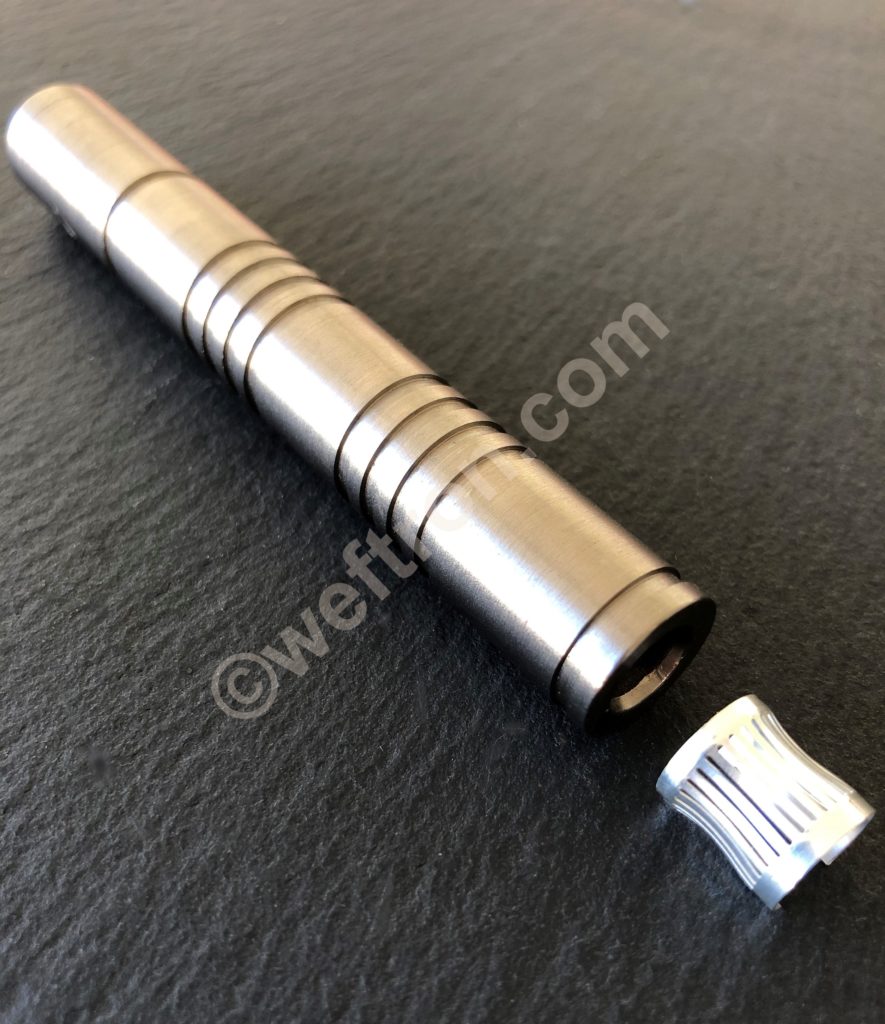
Louvered Contact Band
- Tuning
Metal components for louvertac type contact band need precsion machining. So in addition to very tight dimensional tolerances a very precise and smooth surface is required. Thus limiting surface roughness. Thereafter completed with a high quality connector grade surface treatment.
Each type of louvertac contact band will have a certain range of working height. This working height is established when installing the louvertac contact inside a machined groove. Thus limiting the deflection of the louvers during mating. Preventing the louvers from being deformed or damaged.
The deflection of the louvers will translate into spring force once mated. So recommended groove layout will be provided for a optimal starting point. The fine-tuning of electrical and mechanical performancehowever will need to be established in application testing.
Contact spring compression
As before mentioned this compression value will be achieved by the depth of the groove in which the band rests. Subsequently it is up to the designer of the contact system to find the most suited compression rate for the actual application in which the contact bands are used. Maximum compression provides best power transmission performance but comes with the cost of high mating forces, increased wear on surfaces, lower achievable number of mating cycles and shorter contact life. Minimum compression causes higher higher contact resistance and limits current load capability. Most commonly the best suited value in this trade off is determined in application testing.
The basic features of a contact band are made up by
- the width of the band
- the thickness of the band
- the pitch of the contact bridges (number of contact points over defined length)
- the height of the contact spring elements
- the length of the band is dependent upon its use
It is important to note that the height of the contact spring elements in their virgin (not yet compressed) state will differ from their height after the first few compression cycles.
This difference is referred to as “spring setting” and it is a typical behavior for any type of spring.
After about the first 5-10 compression cycles the spring will reach its working height and should remain close to this height until end of life.
Continue reading on how to calculate nominal current rating ....


