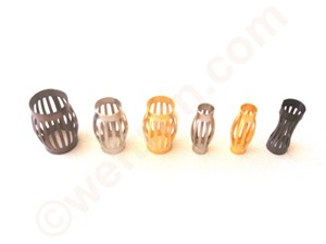
Louvered Contact Band
- Nominal Current Calculation
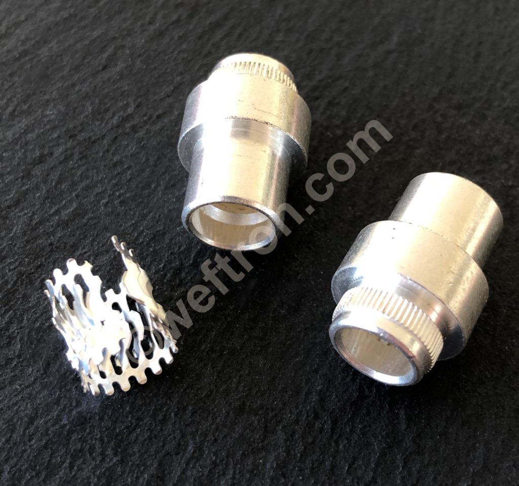
The following examples will show how to determine the nominal performance rating of a High Current Contact for two different types of weftron.com Louver_tron inserts when used with different metal components.
In the example the louvered band is installed inside a socket with a mating pin diameter of 25mm
=> Lay flat length of band = π25 => layflat length is78.5mm
Determine the number of contact bridges that will fit the socket:
Louver_tron 313 has a contact spacing of 2mm => 40 * contact bridges for a diameter 25mm socket.
The performance rating for Louver_tron 313 with a material thickness 0.2mm = 30A/ bridge
when used with silver plated components made of ECU copper.
Louver_tron 317 has a spacing of 2.5mm => 32 * bridges for a diameter 25mm socket.
The performance rating for Louver_tron 317 with a material thickness 0.2mm = 27A/ bridge
when used with silver plated components made of ECU copper.
Calculate nominal performance ratings:
Louver_tron 313 will have a nominal performance rating of 40 times 30A =
1200A when used with copper/silver components**
900A when used with aluminum/silver components**
720A when used with brass/silver components**
Louver_tron 317 will have a nominal power rating of 32 times 27A =
864A when used with copper/silver components**
648A when used with aluminum/silver components**
201A when used with brass/silver components**
Conclusion:
Due to the tighter contact spacing and superior contact bridge design*** Louver_tron 313 will allow for higher performance rating on the same connector footprint.
* for applications in sockets the result of layflat length divided by spacing will be rounded up to the next whole number. When installed on a pin the result will be rounded down.
** with conductivity factor of 1 for copper, 0.75 for aluminum, 0.6 for brass
values are for reference only based on optimal design and machining parameters @ ambient 20°C
The final performance will need to be established in testing.
*** Louver_tron 313 geometric layout allows for one entry point on the top and two exit points on the bottom of each louver which leads to two current paths/louver. Louver_tron 317 has one entry point on top and one on the bottom.
Louvered Contact Band- Performance Calc Read More »
